Logic nand gate working principle & circuit diagram Ladder plc logic motor phase control diagram programming start stop using reverse forward circuit three siemens instrumentationtools system stepper point Design cmos circuit for 3-input nand gate
Nand Gate Internal Diagram
A plc ladder logic program consists of a numberof rungs with each rung Xnor gate circuit diagram using transistor [diagram] circut diagram nand gate
[diagram] circuit diagram nand gate
Nand gates logic using nor gate only input truth table variousLogic nand Logic circuit diagram 4 and gatesSolved: given the stick diagram of a 3-input logic gate, draw its.
Half adder circuit using nand gateBrief switch based nand logic gate circuit 第2节 basic gate function (修订中)Introduction to nand gate.
![3 Phase Motor Control using PLC Ladder Logic - Tutorials Point](https://i2.wp.com/instrumentationtools.com/wp-content/uploads/2018/05/PLC-Ladder-Logic-for-3-Phase-Asynchronous-Motor.png)
Nand gate circuit diagram
Logic nand gate tutorial with nand gate truth table3 phase motor control using plc ladder logic Nand equivalent10 input nand gate png.
Single push button on/off logic exampleWhat is cmos inverter in vlsi Logic nand functionPush button switch based nand logic gate demo circuit for learning.
![3.17* Draw a NAND logic diagram that implements the | Chegg.com](https://i2.wp.com/media.cheggcdn.com/study/c0b/c0b9eca3-9b17-4c2a-817a-6c4f13b1c7b7/image.png)
Mitsubishi plc star delta wiring diagram signed pdf
3.17* draw a nand logic diagram that implements theNand gate diagram Symbol of nand gateNand gate internal diagram.
Implementación de cualquier circuito usando solo puerta nandIntroduction to logic gates Introduction to logic – troubleshooting motors and controls.
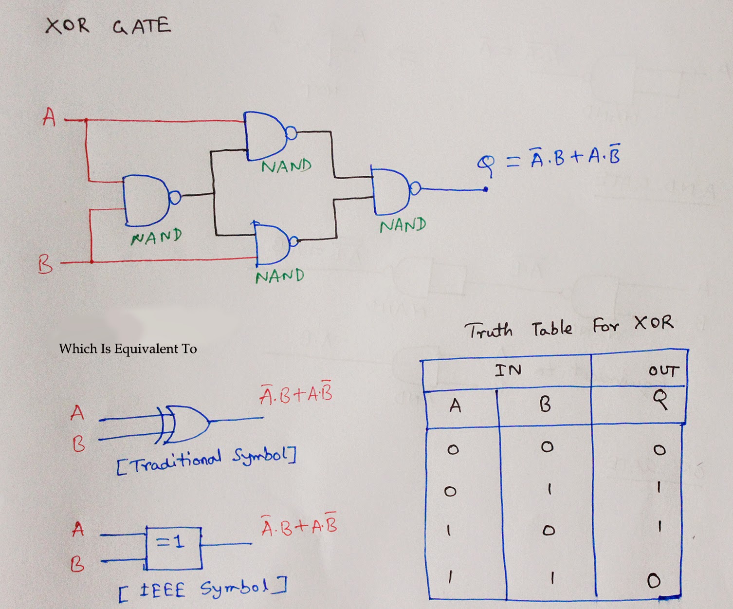
![Half Adder Circuit Using Nand Gate](https://2.bp.blogspot.com/-4RfqzLgPqdE/U4mrdCDNgDI/AAAAAAAABQQ/R8-_f_kDEm8/s1600/XOR+using+NAND.jpg)
![Introduction to Logic – Troubleshooting Motors and Controls](https://i2.wp.com/openoregon.pressbooks.pub/app/uploads/sites/65/2018/12/Logic-NAND.png)
Introduction to Logic – Troubleshooting Motors and Controls
![Design Cmos Circuit For 3-input Nand Gate](https://i2.wp.com/www.electronics-tutorial.net/Digital-CMOS-Design/CMOS-Layout-Design/Layout-of-logic-gates/Fig1-Layout-of-logic-gates.png)
Design Cmos Circuit For 3-input Nand Gate
![Nand Gate Internal Diagram](https://i2.wp.com/www.engineersgarage.com/wp-content/uploads/2020/08/basic-gate-ckt-1536x1235.png)
Nand Gate Internal Diagram
![Logic NAND Function - Electronics-Lab.com](https://i2.wp.com/www.electronics-lab.com/wp-content/uploads/2021/12/NAND-equ.png)
Logic NAND Function - Electronics-Lab.com
![Symbol Of Nand Gate](https://i2.wp.com/electronicsphysics.com/wp-content/uploads/2021/12/2-input-NAND-gate.webp)
Symbol Of Nand Gate
![SOLVED: Given the stick diagram of a 3-input logic gate, draw its](https://i2.wp.com/cdn.numerade.com/ask_images/a1f91bc697e5468c89d8abc61679583a.jpg)
SOLVED: Given the stick diagram of a 3-input logic gate, draw its
![Nand Gate Circuit Diagram](https://i2.wp.com/www.electroniclinic.com/wp-content/uploads/2022/08/a.-NAND-gate-logic-symbol-b.-A-Boolean-expression-for-the-output-of-a-NAND-gate-c.-Truth-table-for-AND-NAND-gate-681x720.jpg)
Nand Gate Circuit Diagram
![Nand Gate Diagram](https://i2.wp.com/i.stack.imgur.com/PwcIE.png)
Nand Gate Diagram
![Introduction to logic gates - projectiot123 is making esp32,raspberry](https://i2.wp.com/projectiot123.com/wp-content/uploads/2019/05/NAND-Gate-truth-table-1.jpg)
Introduction to logic gates - projectiot123 is making esp32,raspberry